SWR – Standing Wave Ratio
Antenna performance is one of the most important parts of any ham radio station. And one of the best ways to ensure proper installation of your antenna and feedlines is by measuring the SWR, or Standing Wave Ratio.
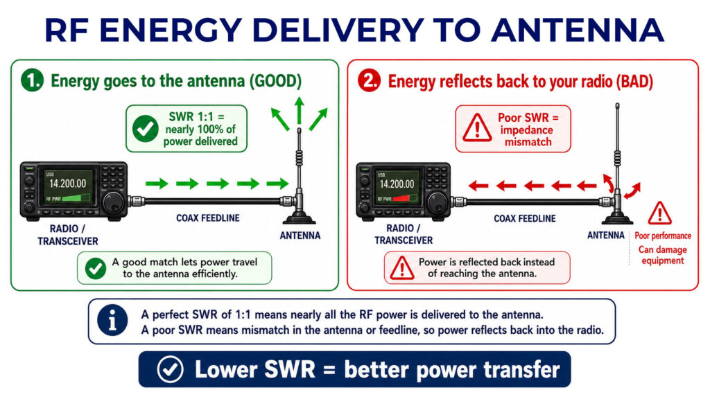
SWR measures how well your radio’s power is being transmitted through the feedline and into the antenna. A perfect SWR of 1:1 means that nearly 100% of the power is being delivered to the antenna, while a poor SWR means that there is an impedance mismatch somewhere in your cables or antenna, and power is being reflected back into your radio instead of going to the antenna. This causes poor performance and can even damage your equipment.
There are various different types of devices you can use to measure SWR, and many radios even have built-in SWR meters.
In my opinion, the easiest way to measure SWR is to connect an SWR meter to your COAX going to the antenna. I always check the SWR when setting up a new antenna, or to troubleshoot if I think there may be a problem with my antenna and feedline.
To use an SWR meter, first set the frequency you plan on using with your antenna. Then the SWR meter will give you a reading.
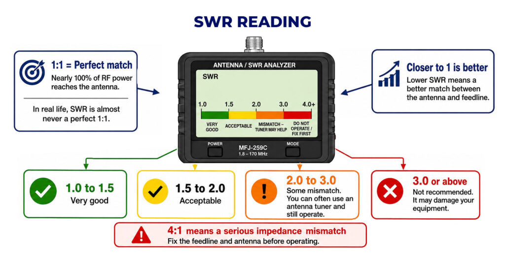
An SWR reading of 1:1 indicates a perfect match between the antenna and the feedline, meaning nearly 100% of the RF power will be delivered to the antenna. In reality, your SWR will never be a perfect 1:1, but the closer you are to a reading of 1, the better.
An SWR reading between 1 and 1.5 is very good. An SWR of 1.5 to 2 is acceptable.
An SWR reading of 2-3 means you have some mismatch, but usually in this range, you can use an antenna tuner and still operate.
It’s not recommended to operate if your SWR is 3 or above, as it can damage your equipment. An SWR reading of 4:1 indicates an impedance mismatch, and you must fix your feedline and antenna before operating.
High SWR means that the power is not being delivered to the antenna, but instead it is being reflected back to your radio, which can damage your radio.
That’s why most solid-state transmitters reduce output power as SWR increases beyond a certain level to protect the RF output amplifier transistors.
If you see that the RF power output from a solid-state transceiver is low, high SWR could be the cause, because the power is being reflected back instead of being delivered to the antenna.
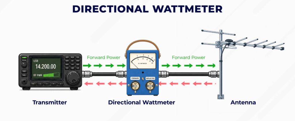
In addition to an SWR meter, you can also use a directional wattmeter to determine SWR. A directional wattmeter measures the power traveling from the transmitter to the antenna (forward power) against the power reflected back due to an impedance mismatch (reflected power back to your radio).
Antenna Analyzer
To better measure your antenna performance, you can use an antenna analyzer to determine if an antenna is resonant at the desired operating frequency.
An antenna analyzer can often scan a range of frequencies and can graph the SWR of your antenna across various frequencies, and some can even give you more advanced information, like inductance and capacitance.
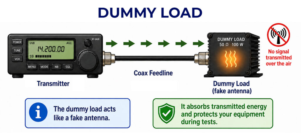
Using a Dummy Load
When testing your transceiver, you can purchase a dummy load as a substitute for an antenna.
The purpose of a dummy load is to prevent transmitting signals over the air when making tests. The dummy load acts like a fake antenna and absorbs the transmitted energy, keeping your equipment safe while allowing you to make test transmissions.
A typical RF dummy load consists of a 50-ohm non-inductive resistor mounted on a heat sink.
- A dummy load is 50 ohms because modern amateur radio equipment is designed for an impedance of 50 ohms
- A dummy load is non-inductive, which means it doesn’t act as an inductor storing magnetic energy, and therefore keeps a steady 50 ohm resistance regardless of the frequency
- And a dummy load has a heat sink because it needs a way to dissipate the radio energy into heat
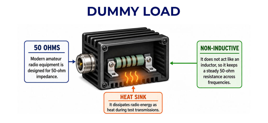
An exam tip for remembering a typical dummy load is remembering that the answer is the only option that has a heat sink!
Feed Lines & Cables
In addition to your antenna and transceiver, feedlines are a critical component of your station.
Feedlines are the physical cables that connect your radio to your antenna, and are usually COAX.
The longer your feedline, the more power you will lose before the signal gets to your antenna, so it is best to keep your feedline as short as reasonably possible. Power lost in the feedline gets converted into heat.
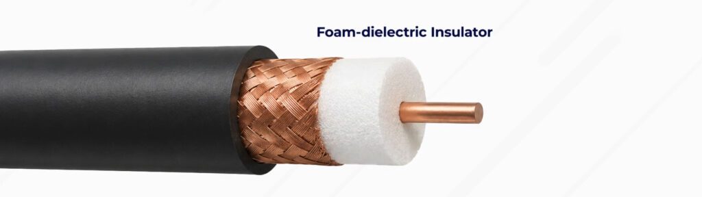
Thicker and higher-quality coax cables also have less signal loss per foot of cable. The material used as the dielectric in the COAX, which is the insulator between the center copper and outer shield, is a factor. Foam-dielectric has less loss per foot than solid-dielectric coaxial cable.
There is one common killer of COAX cables every ham needs to know – moisture.
Moisture contamination can ruin COAX cables, so it is critical to make sure all your COAX connections are tightly sealed and protected from the weather. Moisture can absorb energy, causing poor performance, and it can also cause corrosion of the copper.
The outer jacket of coaxial cable should be resistant to ultraviolet light because ultraviolet light can damage the jacket and allow water to enter the cable.
Basic Test Instruments
For every electrical measurement you need to make, there’s an instrument to measure it.
Voltmeters
A voltmeter is used to measure electrical potential. Remember that voltage is the same as electrical potential and is measured in volts.
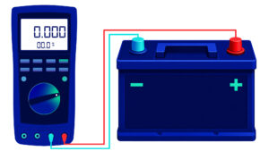
A voltmeter should be connected in parallel with a component to measure the applied voltage. For example, you would connect a voltmeter in parallel across a battery to measure the battery’s voltage.
Ammeter
An ammeter is used to measure electric current. Remember, current is measured in amps.

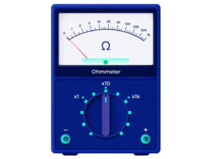
Ohmmeters
An ohmmeter measures resistance.
An ohmmeter works by applying a small current and measuring the resulting voltage.
When you attach an ohmmeter to a large, discharged capacitor, the applied current will begin to charge the capacitor, and the ohmmeter will show an increasing resistance with time.
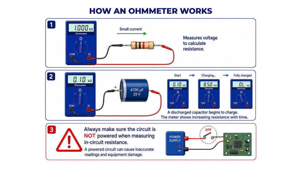
When using an ohmmeter to measure in-circuit resistance, you should always ensure the circuit is not powered. Using an ohmmeter when a circuit is powered could lead to inaccurate readings and equipment damage.
Multimeters
Today, the most common measurement device is a multimeter, which can measure multiple properties like voltage and resistance, all in one device.
However, multimeters do NOT measure signal strength and noise, or impedance and reactance, which are measured with other specialized devices.
Multimeters are affordable online or at your local hardware store.
To measure current, a multimeter should be connected in series with a component, in order to measure the current passing through.
Attempting to measure voltage when using the resistance setting can damage a multimeter.
Solder
One of the exciting aspects of amateur radio is building your own equipment and experimenting with electronics.
We frequently use a technique called soldering when building electronics. Soldering is a way to connect electrical components by using heat from a soldering iron to melt metal, called solder, over the connection point. Once the solder cools, it becomes solid again and forms an electrical connection.
Solder can be used on circuit boards, and I have used it frequently when attaching COAX connectors.
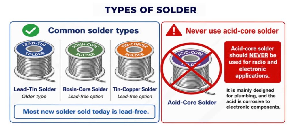
There are different types of solder, made of different materials. Lead-tin solder is an older type of solder, but most new solder sold is lead-free: either rosin-core solder or tin-copper solder.
Acid-core solder should NEVER be used for radio and electronic applications. Acid-core solder is designed primarily for plumbing applications, and the acid is corrosive to electronic components.
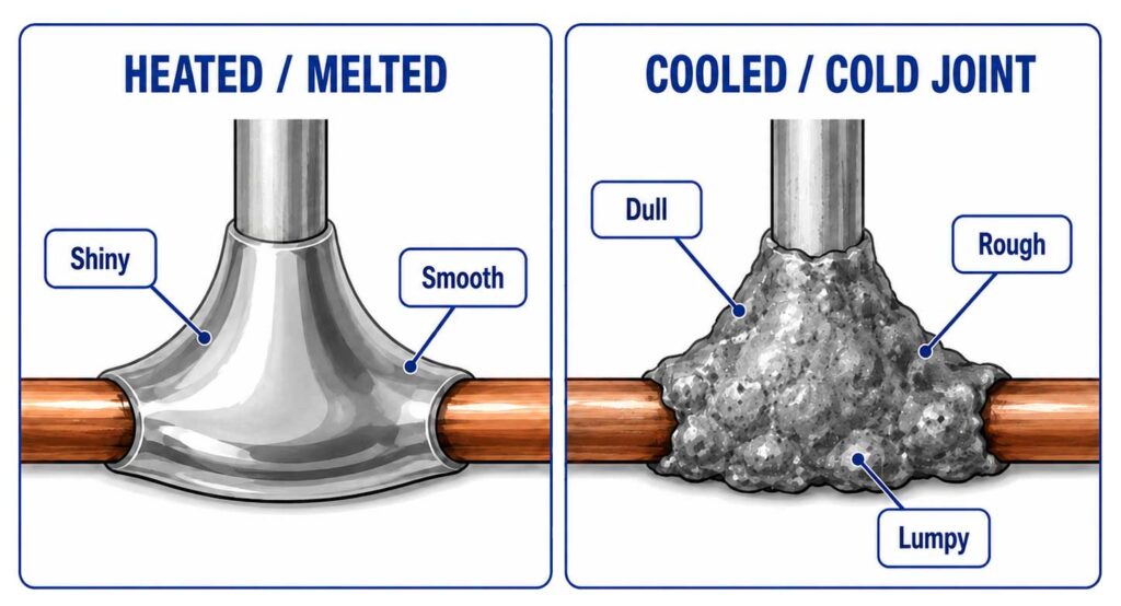
Solder changes appearance when heated and melted versus when it’s cooled and solid. Usually, when it’s heated and melted, the solder appears shiny and smooth. Then it becomes dull and rough as it cools. For example, a cold tin-lead solder joint appears like a rough or lumpy surface when cold.
Lesson Recap
Let’s recap. In this lesson, you learned about measuring SWR, the single most important way to measure your antenna and feedline to make sure they’re set up correctly. An SWR of 1:1 is a perfect match, while an SWR of 4:1 is an impedance mismatch that prevents power from being effectively delivered to your antenna and can cause damage to your equipment.
You learned that you can use a dummy load to test your transceiver without transmitting real signals, and that a dummy load is made of a 50-ohm non-inductive resistor mounted on a heat sink.
We discussed COAX feedlines, and that moisture is a COAX killer every operator should avoid.
You learned that there are various measurement devices, like voltmeters to measure electrical potential and ammeters to measure current, as well as a multimeter, which can measure voltage and resistance in one single device.
Finally, you learned about connecting electrical components using solder, and that acid-core solder is corrosive and should never be used for radio and electronic applications.