Schematic Diagrams
An electrical diagram using standard component symbols is called a schematic.
On the ham radio technician exam, there are three possible circuit diagrams, or schematics, you may be asked about, but you’ll likely only see one diagram question – let’s take a look.
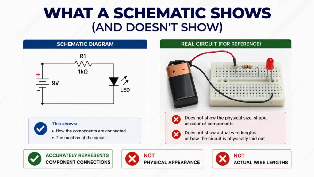
A schematic accurately represents the component connections, it is NOT meant to accurately show the physical appearance of components or actual wire lengths.
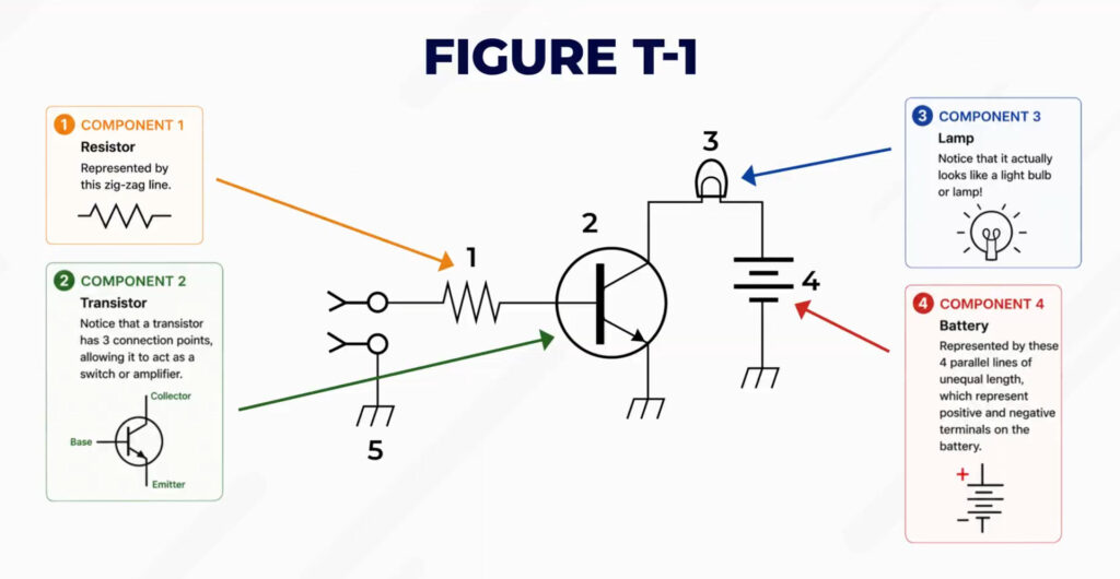
Figure T-1 is the first diagram you may see on the exam.
Component 1 in Figure T-1 is a resistor, represented by this zig-zag line.
Component 2 is a transistor – notice that a transistor has 3 connection points, allowing it to act as a switch or amplifier.
Component 3 is a lamp – notice that it actually looks like a light bulb or lamp!
Component 4 is a battery – represented by these 4 parallel lines of unequal length, which represent positive and negative terminals on the battery.
So what does this circuit actually do?
In this circuit, the function of this transistor is to act as a switch to control the flow of current. When a small voltage is applied to the input terminal, it allows current to flow and turns the light bulb on.
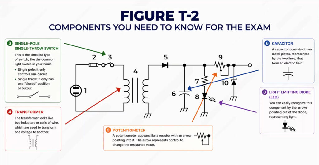
Let’s take a look at Figure T-2, focusing on only the components you need to know for the exam.
Component 3 is a single-pole single-throw switch, which is the simplest type of switch, like the common light switch in your home.
- Single pole means it only controls one circuit, and single throw means it only has one “closed” position or output.
Component 4 is a transformer. Notice that the transformer looks like two inductors or coils of wire, which are used to transform one voltage to another.
Component 6 is a capacitor. A capacitor consists of two metal plates, represented by the two lines, that form an electric field.
Component 8 is a light emitting diode. You can easily recognize this component by the arrows pointing out of the diode, representing light.
Component 9 is a potentiometer, which appears like a resistor with an arrow pointing into it. The arrow represents control to change the resistance value.
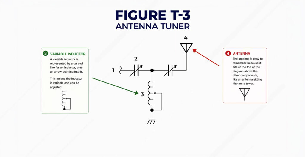
Let’s take a look at Figure T-3, which represents an antenna tuner.
Component 3 is a variable inductor, represented by a curved line for an inductor, plus an arrow pointing into it, representing that it is variable and can be adjusted.
Component 4 at the top is the antenna. This is easy to remember because it sits at the top of the diagram above the other components, like an antenna sitting high on a tower.
Common Circuits
Let’s discuss some common types of circuits used in radio and all of electronics.
![]()
If you look outside your house at the telephone pole, you can probably see a transformer. A transformer is used to convert one voltage to another by using two coils of wire that become magnetically connected.
The transformers outside your house are used to step down the voltage from your street, which is typically between 7,000 and 14,000 volts, to the standard 120V and 240 volts needed in your house.
![]()
A transformer can also be used to change 120V AC power to a lower voltage for other uses.
A transformer does not change between AC and DC current, though. For that, you need a rectifier.
A rectifier is a component that changes alternating current into a varying direct current signal.
A regulator is a circuit that controls the amount of voltage from a power supply. To remember this answer, just think that a regulator regulates the amount of voltage.
A meter is a type of electrical circuit that displays an electrical quantity as a numerical value.
Shielded COAX
In ham radio, we use shielded COAX to connect radios, antennas, and other devices. The shielding is a thin metal layer inside the COAX, which is separate from the main center copper conductor.
The shielding acts as a Faraday cage that protects against electromagnetic interference.
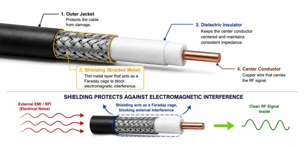
The reason to use shielded wire is to prevent coupling of unwanted signals to or from the wire.
Lesson Recap
In this lesson, we reviewed the three circuit diagrams that you could see on the exam. You learned that a schematic shows component connections, but doesn’t accurately represent physical appearance or wire lengths. You learned the schematic symbols for resistors, transistors, capacitors, inductors, transformers, antennas, and more.
You learned the difference between a transformer, which changes the voltage, and a rectifier, which is used to change from AC to DC, and a regulator, which controls the amount of voltage from a power supply.
Finally, you learned that the reason ham radio operators use shielded COAX is to create a Faraday cage that prevents unwanted signals from entering or leaving the wire and creating interference.