Inductors and Ferrites
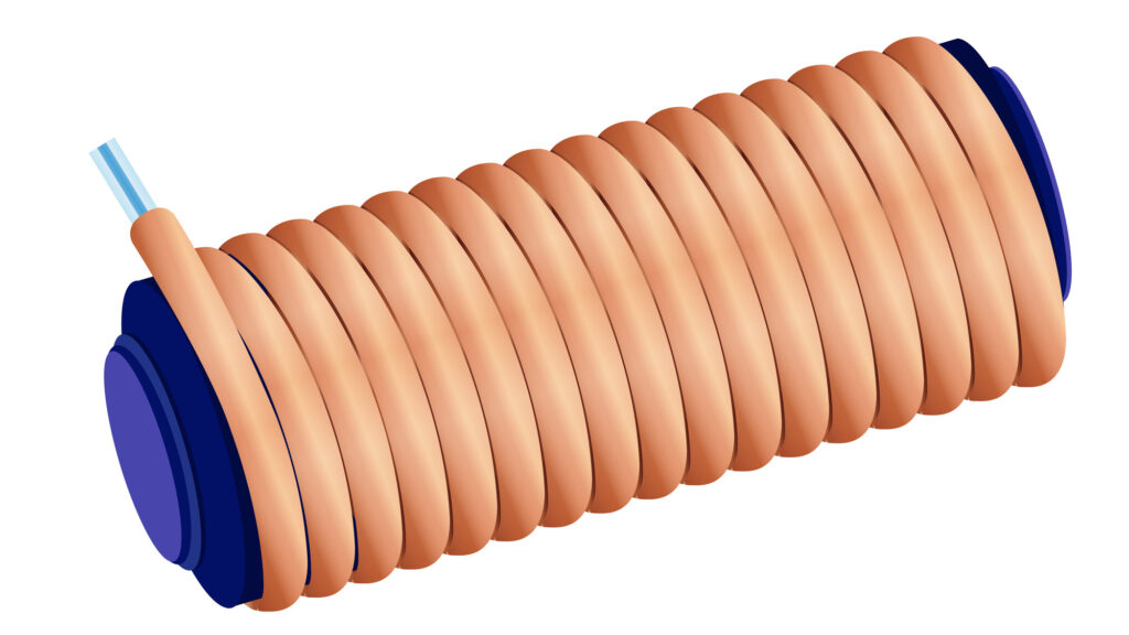
Remember how an inductor works. It’s typically an insulated wire wound around a core that stores energy in a magnetic field. Think of wrapping a wire around a nail – that would create a basic inductor. In this case the nail would be the core.

Wire wound inductor
There are several different materials used for the cores of inductors. Some are ferrite, others are powdered iron, and brass can be used. Core material in an inductor is selected for its permeability. Permeability determines the inductance of an inductor.

Ferrite compound material
Inductor core types are chosen based on their application in the circuit. Why choose ferrite? One reason is that ferrite cores generally require fewer turns to produce a given inductance value. Choose powdered iron for the highest temperature stability of its magnetic characteristics. A choice of brass as a core material is a way to decrease the inductance.
Instead of a ferrite core, this non-conductive material gets used in other ways. One is to help suppress interference. Ferrite beads are commonly used as VHF and UHF parasitic suppressors at the input and output terminals of a transistor HF amplifier. You have seen ferrite beads on cables used for your computer – well, they are also used in ham radio!

Ferrite bead on USB cable
Inductors get named for their form factor. An inductor with wire wrapped around a circular ferrite is a toroidal inductor. Peek inside a power supply or amplifier and you’ll probably see one. Its primary advantage is that toroidal cores confine most of the magnetic field within the core material. A solenoidal inductor is bar shaped and you might find one as part of your phone’s wireless charger. 
Toroidal
Solenoidal
One of the things you may need to troubleshoot for is inductor saturation. This is when the ability of the inductor’s core to store magnetic energy gets exceeded. Inductor saturation is caused by operations at excessive magnetic flux. That happens with too strong a magnetic field.
Multiple inductors can form a device called a transformer. One typical use is to convert AC voltage from high to low or low to high. This is exactly how transformers on utility poles work!
![]()
Common transformer
Let’s consider a typical transformer with two inductors. One inductor is the primary winding, the other is the secondary winding. As current feeds into the primary winding, it is picked up as inductance in the secondary winding. The secondary winding outputs it as a new current level. If no load is attached to the secondary winding of a transformer, the current in the primary winding is called magnetizing current.
Some inductors and transformers use one solid core. Others use thin layers of material instead. That’s often done to reduce power loss from eddy currents in the core.
Resonant Circuits with Crystal Oscillators
You know that LC and RLC circuits have resonance. A popular way to tune a frequency to a particular resonance is to include a crystal oscillator. Millions of crystal oscillators are in use. Find them in watches, clocks, and radios to provide resonant circuits.
A crystal oscillator starts with a finely cut piece of quartz crystal. Energy passed through the quartz provides a stable frequency output. This oscillation is the piezoelectric effect. That is a characteristic of materials that generate a voltage when stressed and that flex when a voltage is applied. The crystal is subjected to mechanical deformation of material by the application of a voltage. That action causes it to vibrate at a known frequency.

Illustration of crystal oscillator
A quartz crystal is a great tool, but you can replace it. The equivalent circuit is a Series RLC in parallel with a shunt C representing electrode and stray capacitance. You can remember this answer by remembering the shunt capacitor.

Illustration of shunt capacitor
Light Sensitive Semiconductors
Semiconductors that are light sensitive get used in photoconductive and photovoltaic materials. The difference between the two is in the names. With photoconductive material, resistance decreases when light shines on it. So it conducts electricity more efficiently. A crystalline semiconductor is most commonly used to create photoconductive devices. One example of this is the sensor that triggers your outdoor lights when it gets dark.
Solar power cells use photovoltaic material. With this material the effect is the conversion of light to electrical energy. That means voltage is generated. Electrons absorb the energy from light falling on a photovoltaic cell.
The silicon photovoltaic cell is the most commonly used for electrical power generation. How much power do you get from a photovoltaic cell? The approximate open-circuit voltage produced by a fully illuminated silicon photovoltaic cell is 0.5 V. The cell’s efficiency is the relative fraction of light that is converted to current. Materials these days have a 10% to 30% efficiency, so up to 30% of light becomes energy.

Illustration of solar panel
Circuit Management Tools
Managing current in a solid-state circuit is often done with an optoisolator. You’ll commonly find an optoisolator or optocoupler configured with an LED and a phototransistor. You’ll frequently see optoisolators used with solid-state circuits that control 120 VAC circuits. This is because optoisolators provide an electrical isolation between a control circuit and the circuit being switched.

Schematic of optoisolator
A common application of an optoisolator is in the form of an optical shaft encoder. This is a device that detects rotation of a control by interrupting a light source with a patterned wheel. You might find one on the main tuning knob of your modern radio.
Circuit noise in a signal can be managed with a comparator. That is a high-gain differential amplifier. The function of hysteresis, or induction lag, in a comparator is to prevent input noise from causing unstable output signals.

Schematic of comparator
The comparator changes its output state when the level of a comparator’s input signal crosses the threshold.
One way to manage voltage in your circuit is using resistors. These “pull-up” or “pull-down” resistors are a resistor connected to the positive or negative supply line used to establish a voltage when an input or output is an open circuit.
