Receiver Performance Characteristics
A good receiver can help you pick out weak signals among other stronger ones on the band. Want to efficiently pick out weak signals? Knowing the characteristics of receiver performance will help.
The characteristic called capture effect takes place with FM receivers. The receiver will generally lock on or “capture” the strongest signal. This is due to how FM is processed. The capture effect happens because other signals are suppressed by the strong signal. Think of a repeater, only one strong signal can be heard at a time. Need to manage unwanted strong signals that are out-of-band or interference? A front-end filter or pre-selector receiver circuit can be effective in eliminating them.
Let’s stay on FM and talk about intermodulation. With intermodulation, two or more signals combine and create interference within your circuit. Technically, nonlinear circuits or devices cause spurious signals in an electronic circuit.
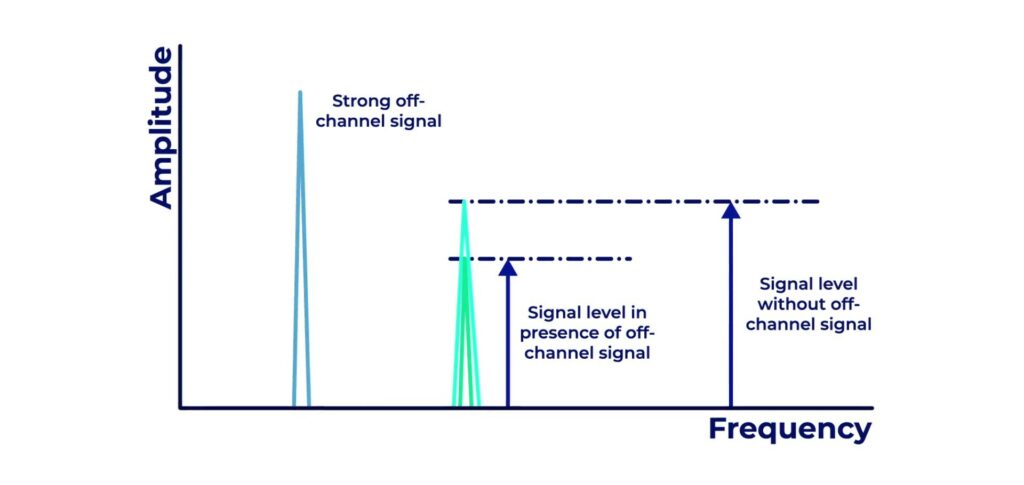 Graph illustrating desensitization
Similar to intermodulation is desensitization. That is the reduction of receiver sensitivity caused by a strong signal near the received frequency.
Imagine two hams are standing next to each other. They are using their handhelds into a repeater. When one transmits, the other doesn’t hear the repeater signal back. This is because of desensitization issues with the receiving radio. Move apart, and they hear just fine.
Do you have two different repeaters near each other? That could cause intermodulation issues! This is because the output signals mix in the final amplifier of one or both transmitters.
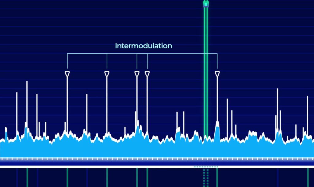
Graph illustrating intermodulation peaks
AM and its single side band component doesn’t have capture effect issues. If two signals are on the same frequency at the same time, you’ll hear a noisy combination of both stations. That’s why aviation still uses AM for air traffic control. Multiple signals can be heard simultaneously.
Shifting to AM and SSB receiver performance. Here, there are two types of receiving circuit to cover. First is a superheterodyne receiver. It uses a step called an IF or intermediate frequency. A local oscillator generates a signal which is mixed with the incoming signal to generate the IF.
Compare that with an SDR or Software Defined Receiver. Many are also called direct receivers because those SDR’s do not use the interim IF step in the receive chain. Some SDR’s do also have a local oscillator.
Both designs have opportunities for multiple signals to enter the receive circuit. Multiple signals bring a concern of noise and how the signals might interfere. Let’s look at a few places where this happens.
It is possible to overload the relatively simple SDR receiver. That happens when input signals exceed the reference voltage of the analog-to-digital converter. That can prevent you from receiving properly.
There’s more to consider with superheterodyne radios. These HF and VHF radios deal with interference on many levels. This is in part due to their local oscillator (LO) and intermediate frequencies (IF).
A local oscillator in your receive circuit is susceptible to reciprocal mixing. This is when you have local oscillator phase noise mixing with adjacent strong signals to create interference to desired signals. Why is excessive phase noise in a receiver’s local oscillator bad? It can combine with strong signals on nearby frequencies to generate interference.
Counter that with benefits of a superheterodyne design. This design makes it easier for front-end circuitry to eliminate image responses. That’s a reception of unwanted signals. The superhet IF shifts signals from a lower carrier wave before final detection is done.
Another superhet advantage? Having a variety of receiver IF bandwidths to select from. By varying the IF bandwidth, receive bandwidth can be set to match the modulation bandwidth, maximizing signal-to-noise ratio and minimizing interference. Does your receiver have IF Shift control? You can use it to reduce interference from stations transmitting on adjacent frequencies.
Even the best radios have a limit to the signal level they can receive. The minimum discernible signal is also called the MDS. Another term would be the receiver noise floor. Noise floor is the level of background noise present before receiving signals. Think of it like the background static level.
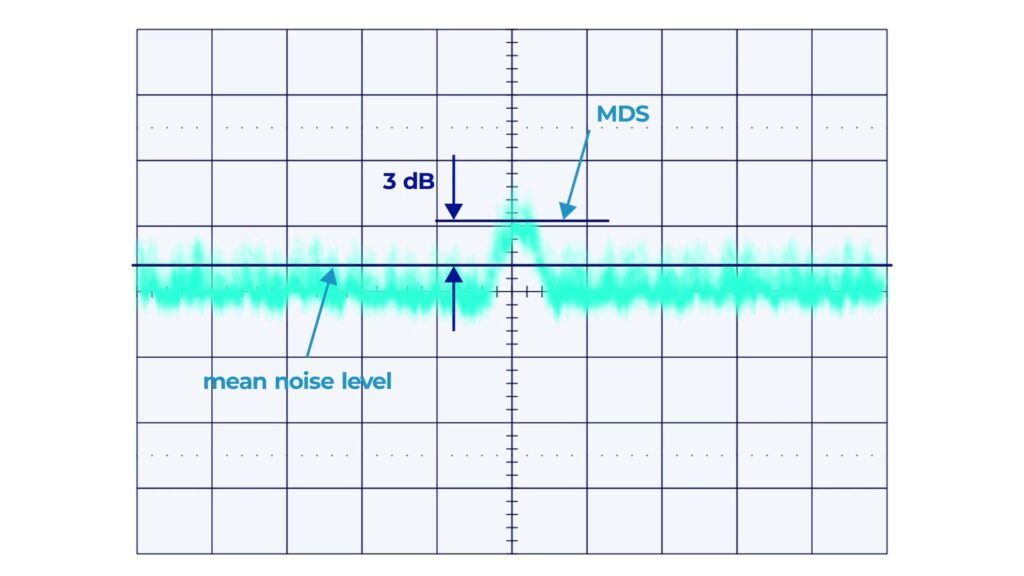
Graph showing minimum discernable signal
Let’s calculate the noise floor of a receiver. It is the ratio in dB of the noise generated by the receiver to the theoretical minimum noise. The resulting MDS is usually shown in calculations as dBm or decibel-milliwatts. That can be converted to a power level in watts. A minimum discernable signal of -100 dBm converts to 0.1 picowatts.
An important receiver noise floor figure is -174 dBm. It represents the theoretical noise in a 1 Hertz bandwidth at the input of a perfect receiver at room temperature.
How can you measure when desensitization will occur? Measure the blocking dynamic range of a receiver. It’s how good the receiver is at blocking out these strong nearby signals up to desensitization. You can calculate the blocking dynamic range, also known as BDR. It’s the difference in dB between the noise floor and the level of an incoming signal that will cause 1 dB of gain compression.
An unwanted, or interfering, signal doesn’t need to be on the receive frequency. For strong signals, they only need to be close to the radios’ receiver duplexer or preselector frequencies. This is the dynamic range in a receiver. If it’s poor, it leads to spurious signals caused by cross-modulation and desensitization from strong adjacent signals. The tip here is, narrow the frequency you are trying to listen on so you will have fewer interference issues. Engineering the right bandwidth in a receiver is important. For instance, if you increase the bandwidth from 50 Hz to 1,000 Hz it increases the noise floor by 13 dB.
Let’s get down into the details and look at measures of circuit performance. When looking at the resonance behavior of an oscillator and series-tuned circuit, technicians look at the Q factor. The Q factor is a measure of the performance of a tuned or resonant circuit. To measure the Q of a series-tuned circuit, the bandwidth of the circuit’s frequency response can be used.
Here’s how intermodulation happens. During the combination of the signals, two sets of frequencies can occur. You’ll get frequencies that are present due to addition. Think 10 MHz plus 10 MHz equals 20 MHz. These are called harmonics or resonant frequencies.
Frequencies can also be created by multiplication. 10 MHz times 2 is 20 MHz. That would be called a second order harmonic. 10 MHz times 3, is, you guessed it 30 MHz and would be a third order harmonic. The first harmonic, 10 MHz and third harmonic, 30 MHz are called odd order products.
These become of particular interest in an RF receiver. Odd-order products of two signals in the band of interest are also likely to be within the band. That makes them very difficult to filter out.
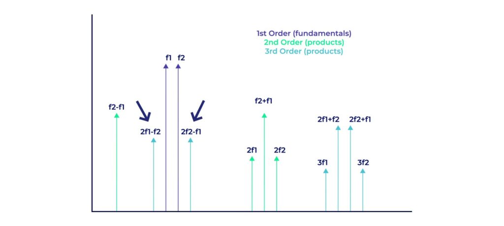
Odd-order graph
An interesting concept in circuit theory is the third-order intercept. It’s a hypothetical point where the power from the original signal and the combined signal from the third order harmonics are the same.
Let’s look at a third-order intercept level of 40 dBm with respect to receiver performance. That means that a pair of 40 dBm input signals will theoretically generate a third-order intermodulation product that has the same output amplitude as either of the input signals.
A high third-order intercept level is good! It means the intermodulation products are less likely to interfere with the main signal. That’s called the first harmonic or fundamental signal.